Prosthetic implant daily full digital

Antonino Cacioppo, DDS, MS, PhD*
* Graduated with Honours in Dentistry and Dental Prosthesis at the University of Palermo in 2006
Masters in Implantology in 2007 Doctor of Research in Dental Stomatology in 2011.
Post-graduate course in Surgery and Guided Implantology at Genoa University Since 2007 he has been engaged in 2D and 3D dental radiodiagnostics, dental practice CAD-CAM and guided implantology Author of 17 international publications and co-author and contributor to books in the field. Speaker in a larger number of national and international congresses, he collaborated with the International Journal of Clinical Dentistry between 2007 and 2013. He has worked in a freelance capacity in Palermo since 2007. Since 2015 he has been a lecturer for the Complex Oral Rehabilitation Programme Masters Programme at the University of Catania. Since 2017 he has been a temporary lecturer at the University of Catania, Prosthesis II Iecturer (sixth year)
One of the most exciting challenges of the time, marked by the digitalisation of dental procedures, is the possibility of bringing digital flows into everyday procedures simply, rapidly and in documented form. Implant surgery and implant prosthesis, specialised disciplines that have been the first to adopt the innovations offered by digitalisation but that often focus on large rehabilitations are no exception. Let's look together at a case that serves as an example of a full digital flow from the diagnosis to the prosthetic rehabilitation of a monoedentulous.
The patient is fifty-four year old woman with a previous history of a treated and stabilised post-oncological periodontal disease. The edentulous saddle presents in position 1.4 with the maintenance of the prosthetic space and thick gingival biotype. On the first visit, first level radiographic imaging (OPT and Intraoral of the edentulous region - Durr VistaScan Mini View image plate scanning system), second level imaging (CBCT 8x5 focussed on the upper arcade, with StandardDose - DentsplySirona Orthophos SL protocol), intraoral optical imprints (DS Omnicam with Cerec 5.1) (Fig. 1) were performed.
Virtual diagnostic waxing of the missing element was done chairside with CEREC 5.1 software. The data was exported in STL format and imported into the 3D Guided Implant Surgery 9.1 software (Medialab). Again chairside, in front of the patient, matching between CBCT and 3D model was performed and the implant position was planned from both prosthetic and anatomical point of view. Given a slight bone defect left by previous dental avulsion, the implant (GHIMAS BNX EVO 4x11.5) is planned with the top platform (a compromise to avoid surgery to manage hard tissues). It must be emphasized that all these procedures performed “live” greatly help to improve communication with patients and to obtain greater compliance and acceptance of treatment plans. On the first visit, the colour is also detected with photographs taken extemporaneously with the “multimedia” lamp (AlyaCam - Faro). Once the implant planning is finished, the surgical template? is modelled and the file is sent to the printer, in house in this particular case but it can often be found in the laboratory or at a prototyping centre (Fomlabs FORM 2). The second session is guided surgery. It was decided to perform flap surgery (crestal flap slightly palatized with mesial and distal intrasulcular discharges) to maintain the excellent keratinized gingival tissue and to be able to manage the greater portion of the bushing present in the surgical guide (fixed distance 5 mm from the platform implant) and to adequately clean up the implant site from residual granulation tissue left by the previous avulsion. The option was chosen for the deferred load with the reopening and positioning of the healing abutment sixty days from the surgery. The healing was maintained for thirty days (Fig. 2.3).
The optical impressions are then taken (it is highly recommended that the provisional phase is bypassed to meet the patient's needs at the time) to be sent to the laboratory for the realization of the screw-retained prosthesis. One of the advantages of the digital flow in this phase is to be able to simultaneously detect multiple impressions aligned directly from the scanning software: impression with healing, impression of the transmucosal path, impression with scan abutment IPD-ProCam Abutmentcompatibili.com (impression of the functionalized provisional if present, in addition of course to antagonist and buccal bite) (Fig. 4) . AbutmentCompatibili.com’s IPD-ProCAm H15mm abutment scan for long transmucosal distances is used for the specific implant platform (Astra TX 3.5 / 4) (Fig. 5.6). The imprints are exported in STL format and sent to the laboratory.
The Lab (Danilo Vaccaro, Palermo) uses ExoCad for all the 3D model modelling and construction phases (Fig. 7, 8, 9, 10). The CrCo-Ceramic prosthetic article glued on the IPD-ProCam interface customised with a mucous height from 2.5 mm and 8mm long bonding stem positioned on the prototype model with 3D print analogies again IPD-Pro-Cam fixed by two screws to the model is received from the laboratory. The article is worn in the mouth without any adjustment or further laboratory phase, opting for the substitution of the traditional titanium screw with the special ceramic TiNCoating covered screw (PD AbutmentCompatibili.com) tightening is done with a torque ratchet at 20/25N/cm recommended by the manufacturer (Fig. 11, 12, 13). Advantage of the digital flow is that it can be standardised and repeatable (after the initial tolerance setting phase). The advantage of the customisation of the devices makes it possible to solve even the most complex clinical situation safely and predictably; the use of an open digital flow is not proprietary of a specific implant manufacture and it furthermore permits the prostheticisation of patients with different implant brands and conditions, something that is more and more common in everyday clinical cases.
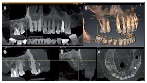 Fig. 1. CBCT diagnostics carried out in the first session.
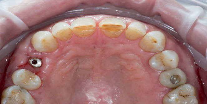 Fig. 2. Occlusal photograph after the insertion of healing abutment on the implant at position 14.
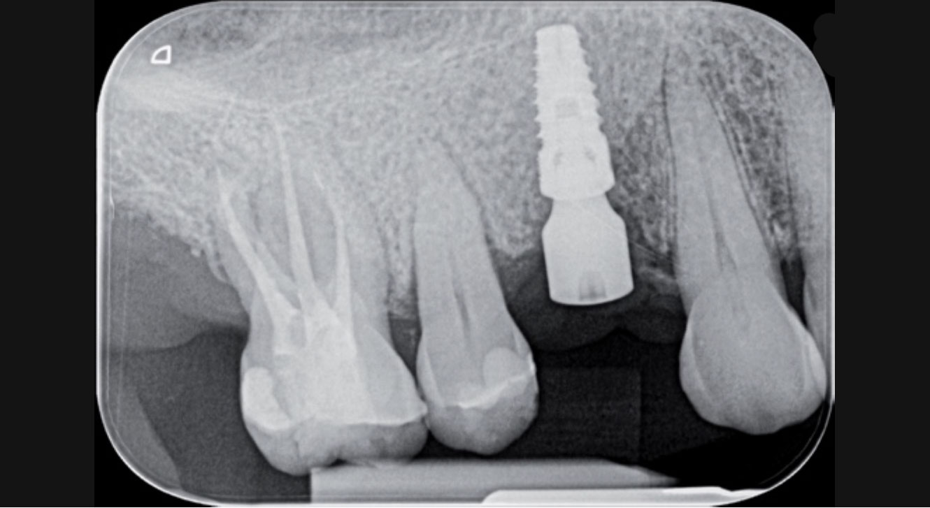 Fig. 3. X-ray to check the peri-implant bone dimension after insertion of the healing abutment.
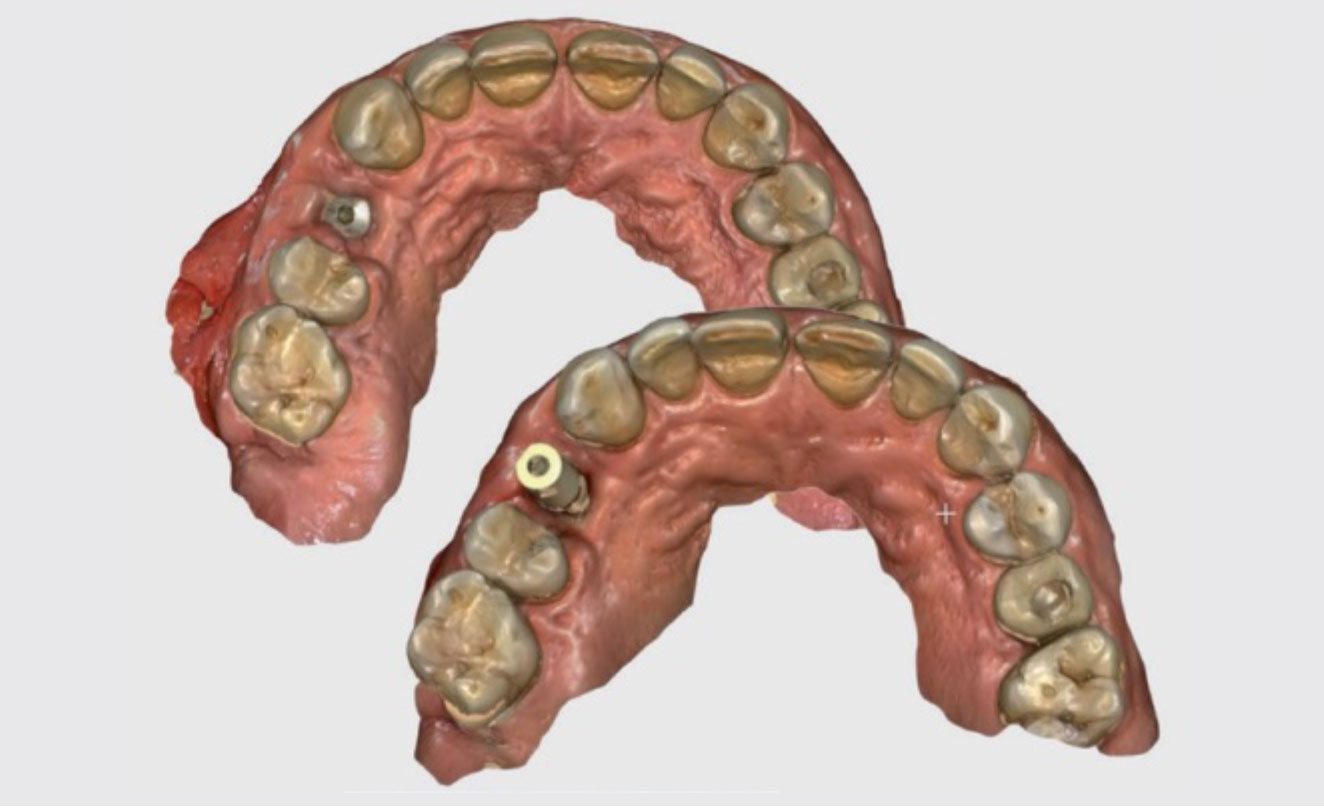 Fig. 4. Intraoral optical imprints (occlusal view). Imprint with healing (left) with scan abutment IPD (right) on implant 14.
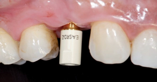 Fig. 5. Scan-abutment screwed on implant in position 14 ready to be scanned.
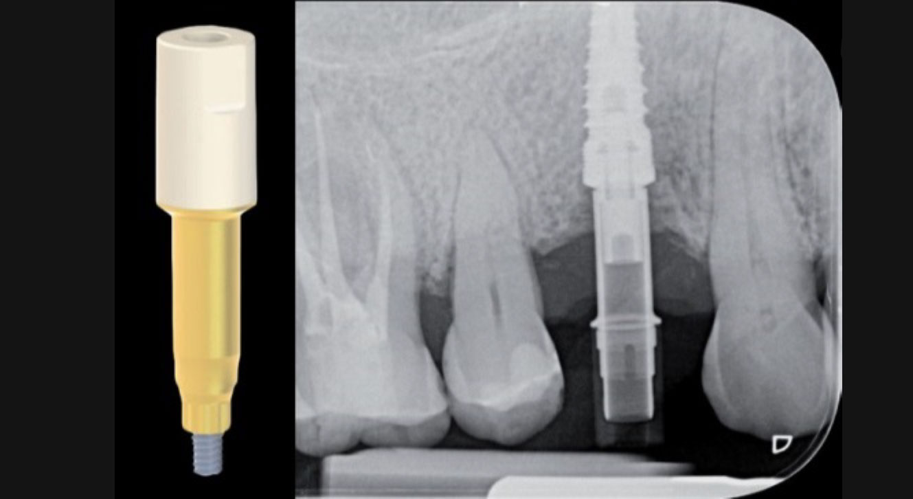 Fig. 6. X-ray to check the correct matching of the IPD scan-abutment.
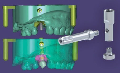 Fig. 7. Detail of the stages in the preparation of the model for 3D printing (with ExoCad software).
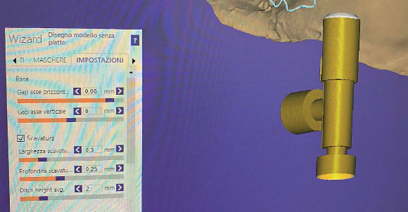 Fig. 8. Settings used for the creation of the model to be used as a prototype with virtual analogue.
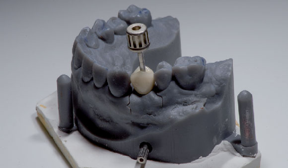 Fig. 9. Prototype model with crown lodged on 14 at the delivery stage.
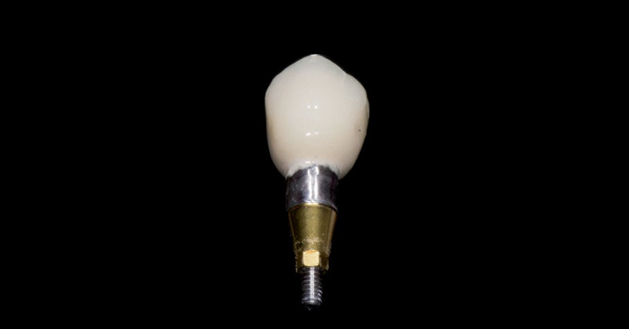 Fig. 10. Ceramic verneered crown on zirconia framwork on IPD Custom Ti Base.
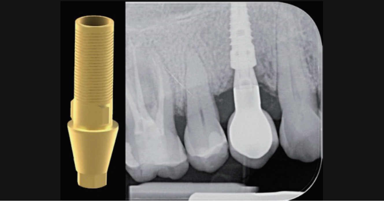 Fig. 11. X-ray for checking the proper matching of the prosthetic crown on the implant in position 14.
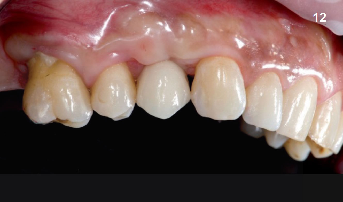 Fig. 12. Photo of the lateral view of the crown screwed to implant 14 (chromatic check and delivery).
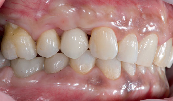 Fig. 13. Photo of the lateral view of the crown screwed on implant 14 in occlusion (contact point check and chromatic integration with antagonistic arcade).